:sales@zsjhsteelgroup.com WhatsApp:+86-15122582058


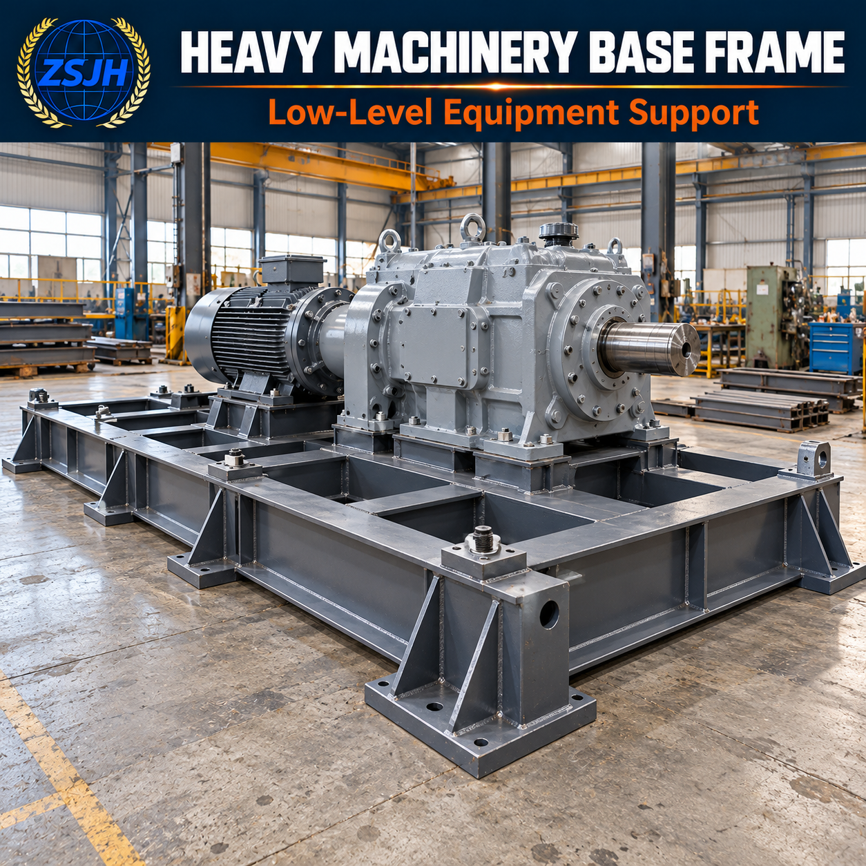


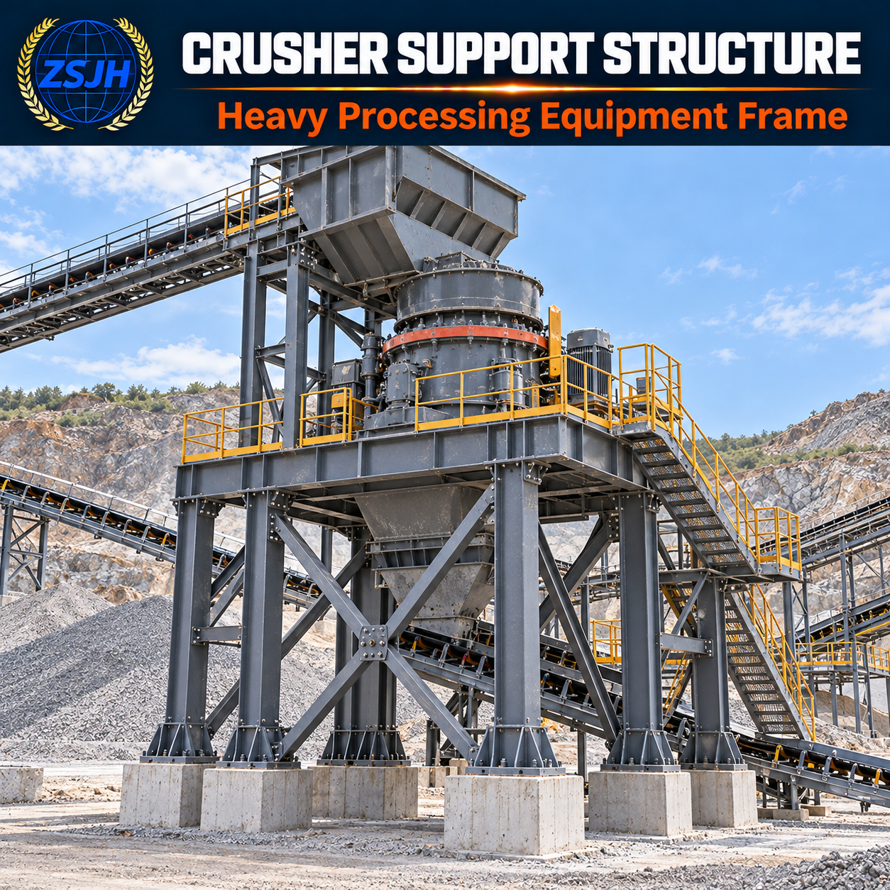


ZSJH supplies custom steel support structures for heavy machinery, process equipment and industrial installations. The structural package can include equipment base frames, supporting columns, transfer beams, bracing, mounting plates and maintenance access platforms, configured to suit the equipment layout and installation requirements.
Each structure is developed around project-specific equipment weights, operating loads, vibration characteristics, mounting interfaces and maintenance clearances. Steel grades, member sizes, connections and protective coatings are specified according to the approved design and service environment.
ZSJH supports drawing coordination, steel fabrication, quality inspection and export packaging within the agreed scope. Supply focuses on the supporting steelwork; machinery and process equipment are included only when separately agreed. Send us your equipment drawings and loading requirements for a tailored quotation.
| Quantity: | |
|---|---|


ZSJH
ZSJH supplies custom heavy equipment supporting steel structures for manufacturing plants, processing facilities and industrial equipment installations. The structural package can include large equipment supports, elevated frames, steel base assemblies, transfer beams, bracing and equipment mounting interfaces.
Each package is configured around the equipment arrangement, loading data and installation requirements. Particular attention is given to equipment weight, operating vibration, maintenance access and connection details, helping coordinate the supporting steelwork with the machinery and surrounding facility.
Large Equipment Supports
Fabricated steel supports carry equipment loads and transfer them to the designated foundations or supporting structure. Configurations can include low-level machinery bases, braced support stands, vessel-support frames and built-up assemblies.
Support locations are coordinated with the equipment manufacturer’s drawings, including mounting points, load distribution and access requirements.
Equipment Supporting Frames
Single-level or multi-level frames can incorporate steel columns, primary beams, secondary members and bracing. The arrangement is developed around equipment elevations, production flow, discharge openings and available installation space.
Member sizes and bracing positions are determined through project-specific engineering, with consideration of structural strength, stiffness and stability.
Equipment Mounting Interfaces
Mounting plates, bolt holes, stiffeners, brackets and connection assemblies are fabricated according to approved interface drawings. Machined bearing surfaces, leveling provisions, shims or grouting interfaces can be incorporated where specified.
Equipment attachment details should be confirmed before fabrication to coordinate bolt patterns, mounting elevations, tolerances and installation access.
Equipment Weight and Load Distribution
The support structure must account for the relevant equipment conditions, rather than equipment self-weight alone. Depending on the application, design inputs may include:
Empty, operating and maintenance weights
Process contents and retained materials
Equipment center of gravity
Reactions at individual support points
Connected piping and auxiliary equipment loads
Installation, lifting or temporary loads where applicable
Concentrated loads are coordinated with mounting plates, transfer beams, stiffeners and supporting columns to establish the required load path.
Operating Vibration and Dynamic Loads
Rotating, reciprocating and impact equipment may impose dynamic actions on its supporting structure. Relevant equipment data can include operating speeds, excitation frequencies, unbalanced forces, impact loads and start-up or shutdown conditions.
Where required, dynamic assessment considers the interaction between the equipment, steel frame and foundation. Stiffness, natural frequencies, fatigue-sensitive details and specified vibration limits are addressed through the applicable engineering scope.
Vibration isolators or damping devices can be accommodated when specified, with their selection and interfaces coordinated with the equipment supplier.
Maintenance Space and Equipment Removal
The frame layout is coordinated with routine inspection and major maintenance activities. Required provisions may include:
Access to motors, bearings, valves and inspection covers
Clearance for removing equipment components
Space for tools, lifting devices and maintenance personnel
Platforms, stairs, handrails and floor openings
Removable members or access panels where engineered and specified
Maintenance loads and temporary equipment positions should be identified during design coordination.
Connections and Installation Requirements
Bolted and welded connections are detailed for the applicable forces, loading cycles and installation conditions. Equipment mounting connections, frame joints and foundation interfaces require coordinated responsibilities and tolerances.
Base plates and anchor arrangements are developed using the specified support reactions and foundation information. Anchor design, concrete capacity and grouting requirements must be addressed within the agreed engineering scope.
| Item | Configuration Basis |
|---|---|
| Structural arrangement | Equipment base, support stand, elevated frame or multi-level support structure |
| Equipment loading | Empty, operating, maintenance and applicable temporary conditions |
| Dynamic requirements | Equipment excitation data, vibration limits and fatigue considerations |
| Main members | Rolled or fabricated sections according to approved design |
| Mounting interfaces | Equipment bolt patterns, support positions, bearing surfaces and elevations |
| Connections | Bolted and/or welded details with specified installation tolerances |
| Maintenance access | Platforms, stairs, clearances and component removal routes |
| Surface protection | Coating or other specified treatment for the service environment |
| Delivery format | Individual marked components or transportable assemblies |
| Documentation | Approved drawings and agreed material and inspection records |
Load capacity, dimensions and vibration performance are project-specific and must be confirmed against the equipment data and approved structural design.
Equipment-specific configuration: Support geometry follows the machinery’s mounting arrangement and operating requirements.
Coordinated installation interfaces: Mounting plates, connections and foundation interfaces are defined before fabrication.
Accessible structural layout: Equipment operation, inspection and maintenance needs are considered together.
Flexible fabrication scope: Steelwork can be supplied as separate members or assembled modules, subject to transport and lifting constraints.
Defined procurement boundaries: Supporting steelwork, access components and optional accessories are clearly listed in the quotation.
Heavy machinery and industrial gearbox supports
Pump, compressor and fan base structures
Process equipment support frames
Vessel and tank supporting steelwork
Crusher and screening equipment supports
Elevated production equipment installations
Modular equipment skid frames
Fabrication follows approved drawings and the agreed technical specification. Inspection can cover material identification, member dimensions, equipment mounting positions, connection hole locations, weld quality and coating application.
Machining, trial assembly and non-destructive testing can be included where specified. Inspection methods, acceptance criteria and documentation requirements are established for each order.
Components are identified and packaged with consideration for handling, transport, unloading and site assembly.
Can you fabricate supports from equipment supplier drawings?
Yes. Equipment drawings can be used to coordinate support positions, mounting details and clearances. Structural fabrication requires approved drawings and confirmed loading information.
Can the structures support vibrating machinery?
They can be engineered for the specified dynamic conditions. Equipment operating data and vibration criteria are required to determine the appropriate structural arrangement and any necessary assessment.
Are maintenance platforms included?
Platforms, stairs, handrails and removable access provisions can be included when defined in the supply scope.
Are machinery and vibration isolators included?
The main product is the supporting structural steelwork. Machinery, isolators, piping and electrical systems are included only when separately specified and agreed.
Can equipment be added later?
Additional equipment or changes in operating loads require a structural review of the frame, connections and foundations before installation.
ZSJH coordinates equipment supporting steelwork around confirmed drawings, loading requirements and installation interfaces. Our support covers fabrication coordination, quality inspection, surface protection and export packaging within the agreed scope.
Clearly defined mounting details and component schedules help buyers coordinate the steelwork with equipment suppliers, foundation contractors and installation teams.
Please provide:
Project location and equipment application
Equipment dimensions, weight and center of gravity
Operating loads and dynamic data, where applicable
Mounting drawings and reactions at support points
Required support height and available installation space
Maintenance clearances and access requirements
Connection, coating and inspection specifications
Supply scope and delivery destination
Send ZSJH your equipment drawings and technical requirements for a project-specific supporting steel structure quotation.


