:sales@zsjhsteelgroup.com WhatsApp:+86-15122582058




| Quantity: | |
|---|---|


ZSJH
Coordinated Secondary Framing. Accurate Connections. Drawing-Based Supply.
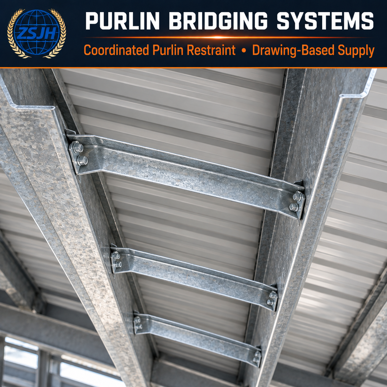
ZSJH Steel supplies custom purlin sag rod and bridging systems for roof purlins and wall girts in steel warehouses, industrial workshops, and pre-engineered buildings. Installed between secondary framing members, these components help maintain alignment and provide the restraint specified in the building design.
Our supply scope includes steel purlin sag rods, diagonal ties, spacer tubes, bridging members, connection cleats, and matching fasteners. Components are configured to approved drawings, with dimensions and connection details coordinated to the C or Z sections used in your project.
Purlin restraint systems can help limit lateral movement and rotation where designed to do so. The appropriate arrangement depends on the section profile, span, loading, cladding connections, and anchorage details.
Correctly dimensioned sag rods and bridging components help installation teams maintain the specified spacing and alignment of roof purlins and wall girts. This supports coordinated cladding installation and reduces avoidable adjustment.
C and Z purlin bridging can be fabricated to match section depth, orientation, hole positions, and connection geometry. Compatibility is checked against the project details rather than assumed from the section name alone.
Sag rods, diagonal ties, spacer tubes, cleats, nuts, and washers can be supplied within one agreed package. Matching components helps reduce missing parts and connection mismatches on site.
Rod diameter, threaded length, tube length, bridging profile, plate thickness, and hole patterns can be tailored to approved drawings. Accurate dimensions are particularly important where components connect multiple rows of secondary framing.
Galvanized finishes or protective coatings can be specified according to the material, component type, and service environment. Thread fit and connection clearances must account for the selected finish.
Roof purlin bracing components can be supplied for the restraint arrangement specified across warehouse roof slopes, including straight sag rods, spacer tubes, bridging members, and diagonal ties.
Coordinated components support roof purlins and wall girts in workshop buildings. Their locations should be checked against skylights, ventilation openings, doors, and building services.
Purlin bridging systems can be manufactured to the building supplier’s approved details and supplied with matching connection hardware.
Suitable for barns, machinery shelters, and storage facilities using cold-formed steel secondary framing, subject to the specified restraint design.
Sag rods, diagonal ties, and bridging components can also be supplied for wall girts. The arrangement must account for girt orientation, wind loading, openings, and supporting connections.
This category is defined by the restraint and stability needs of secondary framing. It covers components connecting roof purlins or wall girts, rather than the main building’s roof or column bracing system.
| Component | Typical Role | Details to Confirm |
|---|---|---|
| Steel purlin sag rods | Tension ties that assist alignment and provide specified restraint | Diameter, length, threads, connection position, and anchorage |
| Diagonal ties | Transfer restraint forces to designated anchor points | Layout, end details, tension capacity, and anchor connections |
| Purlin spacer tubes | Maintain specified separation and provide compression resistance where designed | Tube dimensions, length, bearing details, and compatible rods |
| Bridging members | Connect adjacent members and provide specified restraint | Profile, thickness, length, cleats, and connection geometry |
| Connection cleats and fittings | Connect restraint components to purlins, girts, or anchors | Material, plate thickness, hole pattern, and fasteners |
| Nuts, washers, and bolts | Secure the specified assemblies | Size, grade, finish, quantities, and installation requirements |
Different components provide different types of restraint. A slender sag rod should not be assumed to provide the same compression resistance or rotational restraint as a properly designed bridging assembly.
The performance of purlin anti-sag rods and bridging depends on the complete arrangement, including its connections and anchorage. Connecting adjacent purlins alone does not necessarily establish an effective restraint system.
Before fabrication, confirm:
Purlin or girt profile, depth, thickness, and orientation
Member spacing, span, and roof slope
Number and position of restraint lines
Rod, tube, bridging, and diagonal tie dimensions
Connection hole positions and required clearances
Anchorage at eaves, ridges, frames, or other specified points
Coordination with cladding, insulation, openings, and services
Installation sequence and any temporary restraint requirements
Wind uplift can change which flange is in compression, so restraint requirements must be established for the applicable loading conditions.
Installation should follow the approved details. Excessive tightening of sag rods can distort thin-walled sections. Site drilling, relocation, or removal of restraint components should be reviewed before proceeding.
We review the available drawings to clarify which rods, tubes, bridging members, cleats, and fasteners are required for each roof or wall area.
Fabrication details are coordinated with the specified purlin and girt profiles, including section orientation, spacing, and connection holes.
Custom purlin sag rod assemblies can be supplied to the dimensions and end details shown in approved drawings, helping customers source project-specific components.
Dimensional checks, thread checks, material documentation, and finish inspection can be agreed according to the project specification.
Components can be grouped by type or installation location, with matching hardware and packing arrangements coordinated for overseas delivery.
It helps maintain secondary framing alignment and provides the restraint required by the design. Its effectiveness depends on the member arrangement, connections, and anchorage.
Sag rods generally act as tension ties. Bridging members may provide compression resistance and rotational restraint where their profiles and connections are designed for those functions. They are not automatically interchangeable.
Yes, when specified for the application. Roof and wall arrangements may require different layouts, connection details, and anchorage.
They can be fabricated for either profile. Section dimensions, orientation, spacing, and hole positions must be provided to confirm compatibility.
No. They do not replace adequate purlin sizing. Gravity deflection, wind uplift behavior, and member stability must be assessed as part of the roof design.
Diagonal ties can transfer restraint forces from rods or bridging lines to designated anchor points. Their need and location depend on the engineered restraint arrangement.
Spacer tubes maintain the specified distance between members and may carry compression where designed to do so. Tube length, end bearing, and rod compatibility must match the approved detail.
Not automatically. Main roof bracing and secondary member restraint serve different functions. Any shared function must be demonstrated in the structural design.
Yes. Send the section details, layout, component dimensions, material requirements, quantities, and connection drawings for review and quotation.
Moving or removing a component may alter the restraint arrangement. The responsible engineer or system designer should approve the revised detail.
Looking for a purlin bridging supplier for your roof and wall framing?
Send ZSJH Steel your secondary framing drawings or component schedule. We will review the supply scope and prepare a quotation for the specified rods, spacer tubes, bridging members, and matching connections.
For an accurate quotation, please provide:
Roof purlin and wall girt section details
Member spacing, spans, orientation, and roof slope
Restraint layout and anchorage details
Rod diameters, lengths, and threaded end requirements
Spacer tube and bridging member dimensions
Cleat drawings and fastener specifications
Quantities, finishes, and inspection requirements
Delivery destination and required schedule
If detailed drawings are still being developed, share the available framing layout so we can identify the information needed to define the fabrication scope.
Send Your Drawings • Match Your Framing • Request a Quotation


