:sales@zsjhsteelgroup.com WhatsApp:+86-15122582058




| Quantity: | |
|---|---|


ZSJH
Defined Load Paths. Coordinated Connections. Stable Steel Frames.
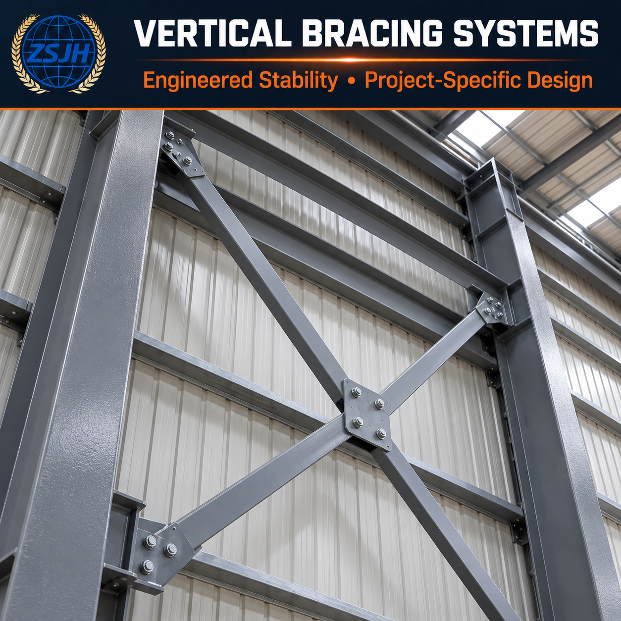
ZSJH Steel supplies custom column bracing systems for steel warehouses, industrial workshops, and portal frame buildings. Installed in vertical planes between columns, these systems provide a load path for transferring specified horizontal forces toward the foundations and maintaining lateral stability.
Our supply scope includes column cross bracing, single diagonal braces, structural tension rods, and matching connection components. Bracing arrangements, member sizes, and connection details are fabricated to approved project drawings, with protective finishes suited to the service environment.
Steel column bracing works with roof bracing, connecting members, columns, and foundations to resist specified horizontal actions. A coordinated system helps control longitudinal movement and transfer forces through designated braced bays.
Column cross bracing and single diagonal bracing can be supplied to suit the approved layout. Tension rods, angle sections, and hollow sections offer different structural behavior; the appropriate member type depends on calculated forces, loading direction, and restraint conditions.
Gusset plates, end plates, clevises, bolts, and adjustment fittings can be supplied with the braces as specified. Matching components help customers manage connection interfaces and reduce procurement omissions.
Brace lengths, section dimensions, plate thicknesses, hole positions, and end details are manufactured to approved drawings. Particular attention to connection geometry helps reduce avoidable cutting, drilling, and adjustment on site.
Protective painting or hot-dip galvanizing can be specified according to exposure conditions and project requirements. Coating details should be coordinated with threaded parts, mating surfaces, and bolted connections.
Component identification and grouped connection hardware can be coordinated with the project’s assembly sequence, helping installation teams locate the correct braces and fittings for each bay.
Column bracing for steel warehouses supports longitudinal stability in designated wall bays. Bracing locations should be coordinated with loading doors, vehicle routes, and future access requirements.
Vertical bracing systems provide stability for workshop frames subject to specified wind and operational actions. Where cranes are present, any crane-related forces and additional restraints must be addressed in the structural design.
Portal frame column bracing connects the roof-level stability system to the foundations through the sidewall braced bays. Its layout must be coordinated with roof bracing and any required transfer members.
Suitable for machinery shelters, agricultural buildings, and material storage facilities where the approved design specifies vertical steel bracing between columns.
Drawing-based fabrication can also support commercial and infrastructure projects using vertical bracing. Multi-storey and seismic applications require project-specific detailing and design requirements.
This category covers steel bracing installed in vertical planes between columns. Its defining function is to provide lateral stability and a vertical-plane load path for horizontal forces.
| Item | Supply and Customization Scope |
|---|---|
| Bracing configuration | Cross bracing, single diagonal bracing, or other approved arrangements |
| Member types | Structural tension rods, angle sections, hollow sections, or specified fabricated members |
| Adjustable components | Threaded ends, turnbuckles, clevises, and compatible fittings where specified |
| Connection components | Gusset plates, end plates, bolts, nuts, washers, and other detailed hardware |
| Dimensions | Brace lengths, section sizes, plate thicknesses, hole patterns, and end geometry |
| Materials | Steel and fastener grades specified in the project documents |
| Surface treatment | Protective painting or hot-dip galvanizing, subject to project requirements |
| Supply format | Individual braces, complete braced-bay packages, or coordinated building supply |
Roof-plane bracing, purlin sag rods, and column flange stays perform different functions and should be listed separately in the supply scope.
The effectiveness of steel building wall bracing depends on the complete load path, including the braces, connections, columns, column bases, and foundations.
Before fabrication, the design should establish:
Braced-bay locations and connection elevations
Column spacing, building height, and brace geometry
Design forces and whether loading can reverse direction
Coordination with roof bracing and transfer members
Clearance around doors, windows, services, and equipment
Connection details, fabrication tolerances, and installation requirements
Slender tension rods should not be assigned compression resistance. A single diagonal brace must be designed for the forces it will experience, including reversed loading where applicable.
Brace adjustment, bolt tightening, and temporary stability measures should follow the approved erection procedure. Permanent bracing does not automatically remove the need for temporary erection bracing.
We review the available drawings and procurement requirements to clarify member quantities, connection interfaces, finishes, and delivery expectations before fabrication.
Our supply focuses on the details that affect assembly: brace length, section size, hole alignment, end fittings, and compatibility with the supporting frame.
As a steel column bracing supplier, ZSJH Steel can provide specified braces together with matching plates and fasteners, simplifying procurement for overseas projects.
Material documentation, dimensional inspection, weld inspection, and coating checks can be agreed according to the project specification.
Component identification, packing arrangements, and logistics coordination help customers prepare for receiving and assembling the supplied bracing components.
Column bracing provides lateral stability and transfers specified horizontal forces through vertical braced bays toward the foundations. It forms part of the building’s overall stability system.
Column bracing is installed in vertical planes between columns. Roof bracing is installed within the roof plane and transfers forces to the vertical bracing system, directly or through designed transfer members.
Cross bracing uses two intersecting diagonals. In a tension-only arrangement, different diagonals resist different loading directions. Single diagonal bracing uses one diagonal, whose member and connections must be designed for the applicable forces, including compression where required.
Yes, where the structural design specifies tension-only bracing. Rod sizes, end fittings, adjustment details, and bracing arrangements must match the approved design.
Changing the location or removing a brace alters the load path. The responsible structural engineer must approve a revised arrangement, which may require another braced bay, transfer members, or a moment-resisting frame.
Yes. Please provide approved member schedules and connection drawings, including dimensions, material grades, quantities, and finish requirements.
They can be included in the quotation when specified. Confirm whether plates are supplied loose or attached to the main frame, and identify bolt grades, dimensions, and quantities.
Column bracing can form part of a seismic-force-resisting system when specifically designed and detailed for that purpose. Standard braces should not be assumed to meet seismic requirements without the relevant engineering specification.
Member sizes, steel grades, connection complexity, quantities, finishes, inspection requirements, and delivery scope affect pricing and production time. These can be confirmed after drawing review.
Need column bracing that matches your steel frame and connection details?
Send ZSJH Steel your drawings or bracing schedule for a quotation covering the specified members, connection components, and protective finish.
For an accurate quotation, please provide:
Project location and applicable design standard
Column spacing, building height, and braced-bay layout
Brace types, sizes, lengths, material grades, and quantities
Connection drawings and fastener specifications
Design forces if engineering support is requested
Surface treatment and inspection requirements
Delivery destination and required schedule
If detailed drawings are still being developed, share the available frame layout and project requirements so we can identify the information needed to define the fabrication scope.
Send Your Drawings • Confirm the Supply Scope • Request a Quotation


