:sales@zsjhsteelgroup.com WhatsApp:+86-15122582058






| Quantity: | |
|---|---|


ZSJH
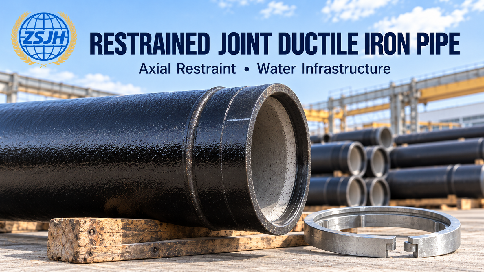
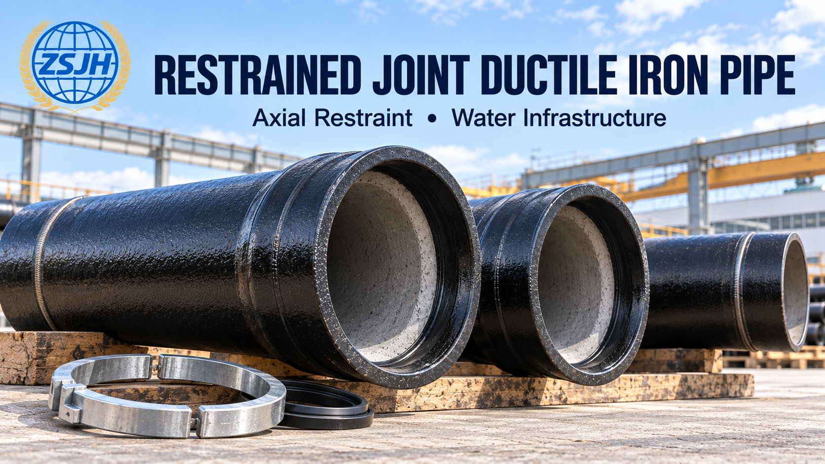
ZSJH supplies restrained joint ductile iron pipes for water infrastructure projects requiring both watertight sealing and resistance to axial joint separation. Unlike a standard non-restrained push-on connection, the restrained joint incorporates a mechanical locking system to transfer axial forces between adjoining pipes.
For procurement teams, the key selection criteria are locking-system compatibility, allowable joint pressure, axial restraint capacity and permitted angular deflection. Pipe diameter and pipe class must be considered together with these joint-specific performance requirements.
In a bead-type design, the pipe spigot has a factory-applied circumferential retainer bead. A compatible metal locking ring or locking segments engage behind the bead within the specially designed socket.
When an axial separation force develops, the bead bears against the locking components, transferring the force to the adjoining socket. A separate rubber gasket provides the watertight seal.
The main components are:
Restrained socket: incorporates the chambers or recesses required for sealing and mechanical restraint.
Prepared spigot: includes the specified retainer bead, chamfer and insertion reference.
Rubber sealing gasket: seals between the socket and spigot.
Metal locking ring or segments: provide the mechanical resistance to axial separation.
Other restrained push-on joint designs use metallic gripping inserts to engage the spigot surface. Depending on the system, a retainer bead may not be required.
These are different joint arrangements. Sockets, spigots, gaskets and locking components must be supplied as a qualified, compatible system rather than combined solely by nominal diameter.
The following designations are common specification examples. Availability and performance depend on the selected product configuration.
| Parameter | Common Marking or Example | What Buyers Should Confirm |
|---|---|---|
| Product type | Restrained Joint Ductile Iron Pipe; Self-Anchored Ductile Iron Pipe | Exact joint design and manufacturer’s identification |
| Nominal diameter | DN100, DN150, DN200, DN300 and other project sizes | Required DN, outside diameter and hydraulic bore |
| Pipe class | C25, C30, C40; K9 where specified | Applicable standard, edition and pipe wall specification |
| Locking system | Retainer bead with locking ring/segments; gripping-insert system | Compatible socket, spigot and locking components |
| Allowable operating pressure | PFA, where used in the EN/ISO product system | Declared value for the selected DN and restrained joint |
| Allowable maximum pressure | PMA, where applicable | Maximum permissible pressure, including surge |
| Allowable site test pressure | PEA, where applicable | Permitted hydrostatic test pressure after installation |
| Axial restraint capacity | Manufacturer-declared allowable axial load, where provided | Rating, units, test basis and applicable joint configuration |
| Angular deflection | Manufacturer-declared angle per joint | Permitted deflection at the required diameter and pressure |
| Pipe length | Specified effective laying length | Length, tolerance and any special preparation requirements |
| Internal lining | Cement mortar lining or specified alternative | Water chemistry and water-contact requirements |
| External protection | Specified metallic coating and finishing layer, or special protective system | Soil conditions and coating requirements |
| Accessories | Sealing gaskets, locking rings/segments, retainers and lubricant | Complete supply quantities and compatibility |
| Documentation | Dimensional records, material tests and joint performance evidence | Required inspection and acceptance documents |
Restrained Joint Ductile Iron Pipe, DN200, Class C40, bead-type locking system, to EN 545, with specified internal lining and external coating. Joint pressure ratings and permitted angular deflection to be confirmed.
This example describes the required information; it does not establish a pressure rating or a universally interchangeable joint model.
An axially restrained ductile iron pipe is designed to resist longitudinal separation within the declared limits of its locking system. The rubber gasket seals the joint; the mechanical restraint components carry the axial force.
For a dead end, pressure thrust is related to internal pressure and the effective internal area. Bends, tees and reducers create different thrust conditions, which must be assessed in the pipeline design.
When reviewing anti-pull-out performance, request:
The declared joint rating for the selected diameter
Supporting qualification or test information
Any limits associated with pipe class or angular deflection
Installation requirements for engaging the locking system
Restrictions on field-cut pipes or site-prepared spigots
A successful leak-tightness test alone does not establish the joint’s axial restraint capability.
Pipe class alone does not establish the restrained joint’s pressure rating.
Select the system against the required operating, surge and site test conditions. Where PFA, PMA and PEA are used, confirm the values in the data sheet for the actual diameter, joint design and pipe configuration.
The applicable system limit must consider the pipe, restrained joint, fittings, valves and other connected components. Pressure ratings from a different diameter or joint family should not be transferred to the offered product.
For AWWA-based projects, review the manufacturer’s working-pressure, surge and test limits under that specification system rather than assuming direct equivalence with EN/ISO designations.
| Standard | Relevance |
|---|---|
| EN 545 | Ductile iron pipes, fittings, accessories and joints for water pipelines |
| ISO 2531 | Ductile iron pipes, fittings, accessories and joints for water applications |
| ISO 10804 | Design rules and type testing for restrained joint systems for ductile iron pipelines |
| ISO 4179 | Cement mortar lining for ductile iron pipes and fittings |
| ISO 8179 series | External zinc-based protection for ductile iron pipes |
| ANSI/AWWA C151 | Ductile iron pipe requirements within the AWWA system |
| ANSI/AWWA C111 | Rubber-gasket joint requirements within the AWWA system |
| ANSI/AWWA C104 | Cement mortar lining within the AWWA system |
Specify the required standards and editions in the enquiry. For an EN 545 restrained joint ductile iron pipe or ISO 2531 restrained joint ductile iron pipe, also request the applicable restraint-system qualification and performance data.
Potable-water approvals for the gasket, lining, lubricant and other water-contact materials should be confirmed separately according to destination requirements.
Restrained ductile iron water pipe can be specified for sections of a pressure network where axial joint separation must be controlled.
Changes in direction, cross-section and flow termination generate hydraulic thrust. Restrained joints can form part of the designed thrust-restraint arrangement.
Specified restrained pipe sections can help transfer axial forces near valves and pumping infrastructure. Equipment connections and supports must be reviewed as part of the complete installation.
Self-anchored ductile iron pipe may provide an alternative where concrete thrust blocks are difficult to accommodate, subject to a project-specific restraint design.
Selected joint systems may be qualified for casing installations or other special methods. Pulling loads, allowable deflection and installation suitability must be verified for the proposed system.
Restrained length is an engineering requirement. It depends on pressure, fitting geometry, soil properties, cover, bedding and other project conditions; installing one restrained joint beside a fitting is not automatically sufficient.
Mechanical resistance to axial separation: adds a defined restraint function beyond ordinary gasket sealing.
Joint flexibility within rated limits: selected systems accommodate limited angular deflection while maintaining restraint.
Coordinated pipe and fitting selection: compatible restrained fittings can extend the restraint arrangement through the required pipe sections.
Potential installation advantages: a qualified restraint design may reduce reliance on concrete thrust blocks in suitable applications.
Clear performance-based procurement: joint ratings and installation requirements allow buyers to compare proposed configurations.
Specification-led sourcing
Provide the required diameter, pressure conditions and restraint arrangement so the enquiry can be matched to an appropriate product configuration.
Coordinated components
Discuss pipes, restrained fittings, sealing gaskets, locking components and lubricant together, with supplied items clearly identified in the quotation.
Technical information for review
Identify the drawings, pressure tables, joint qualification records and inspection documents needed for your project before placing an order.
Export supply coordination
Discuss packing, protection of sockets and prepared spigots, accessory identification and shipping arrangements as part of the supply package.
ZSJH welcomes enquiries from contractors, distributors and procurement teams seeking a restrained joint ductile iron pipe supplier for water infrastructure projects.
A standard push-on joint provides gasket sealing but generally has no designed longitudinal restraint. A restrained joint adds a qualified locking mechanism to resist axial separation.
No. Bead-type systems use a retainer bead with compatible locking components. Other systems use gripping inserts. The spigot preparation must follow the selected design.
The value depends on diameter, joint design and product configuration. Request the actual joint pressure table and check operating, surge and site test conditions.
Do not assume this. Confirm the declared performance of the complete restrained connection for the selected diameter and configuration.
They may reduce or replace thrust blocks where the complete restraint arrangement has been designed accordingly. Required restrained lengths and soil interaction must be assessed.
Only under the selected system’s approved procedure. Bead-type systems may require an approved replacement bead or a suitable special pipe. Cut-end diameter, chamfer, lining and coating repairs also need attention.
Only where compatibility and performance have been explicitly verified. Matching DN alone does not establish compatibility between socket geometry, gasket profiles and locking components.
Many systems permit limited angular deflection, but the allowable angle depends on the product. Follow the specified assembly sequence and deflection limits.
No. Axial restraint alone does not establish seismic performance. Seismic applications require specifically qualified products and an appropriate pipeline design.
Check gasket seating, insertion depth, locking-component engagement and any required joint pull-back or seating step. Use the manufacturer’s instructions and inspect the completed connection before backfilling.
Send ZSJH your specification, pipeline drawings or bill of quantities for a project-specific offer.
Please include:
Required standard and edition
DN, pipe class, length and quantity
Preferred or specified restrained joint design
Operating pressure, maximum surge pressure and site test pressure
Required axial capacity or restraint design information
Permitted angular deflection requirements
Required restrained fittings and accessory quantities
Internal lining, external coating and gasket requirements
Potable-water approvals and inspection documents
Field-cutting or special installation requirements
Delivery destination and target schedule
Request a Quotation for Restrained Joint Ductile Iron Pipe
Share your pressure conditions and connection requirements so the proposed joint system can be reviewed against your project specification.


