:sales@zsjhsteelgroup.com WhatsApp:+86-15122582058








| Quantity: | |
|---|---|


ZSJH
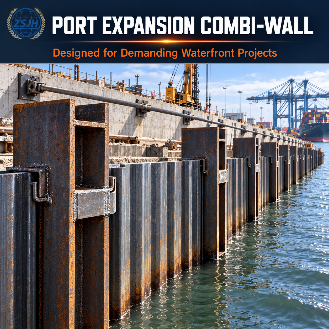
King piles are installed at designed intervals and act as the principal structural members of the wall. Available configurations may include:
Heavy H-section king piles
Fabricated H or box-section piles
Large-diameter tubular king piles
Project-specific built-up steel sections
Interlocking sheet piles are installed between the king piles. Their functions may include:
Retaining soil or backfill
Providing wall continuity
Reducing loss of retained material
Transferring pressure toward the king piles
Contributing to seepage control when appropriately treated
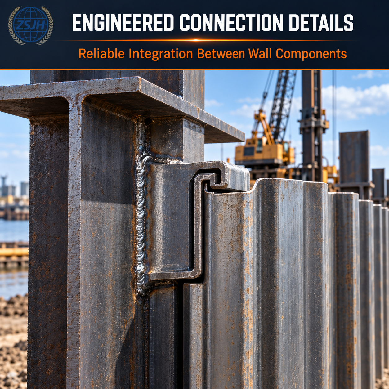
Connector sections are welded or otherwise incorporated along the king piles to receive the edges of the infill sheet piles. Connector selection must be compatible with:
King-pile geometry
Infill-pile interlocks
Installation tolerances
Driving sequence
Required wall alignment
Corrosion-protection system
Depending on the project, the combined wall may operate as:
A cantilever wall
A tie-rod anchored wall
A ground-anchored wall
An internally braced excavation wall
A wall connected to a relieving platform or superstructure
Anchor forces, waler design and connection details are project-specific.
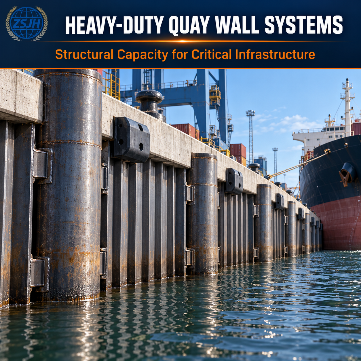
Permanent quay walls may also incorporate:
Reinforced-concrete capping beams
Mooring bollards
Marine fenders
Tie rods and anchor walls
Cathodic-protection components
Utility ducts and service corridors
Drainage and filter systems
Large H-sections or tubular king piles can provide substantially greater wall stiffness than many conventional single-section sheet-pile walls.
The king piles primarily resist major structural actions, while the infill piles retain soil and complete the wall between the primary members.
Combined walls can be configured for substantial exposed wall heights and deep embedment where verified by engineering design.
King-pile type, spacing, infill profile, connector arrangement, anchor system and corrosion protection can be coordinated for the project.
King piles are installed at calculated intervals rather than continuously. The spacing depends on the selected infill section and structural design.
The system can be connected to capping beams, tie rods, anchor walls, relieving platforms, fenders and other port components.
Primary and intermediate elements can be supplied in project-specific lengths, subject to manufacturing, handling, splicing and transportation limitations.
Combined steel sheet pile walls are suitable for:
Deep-water container terminals
Bulk-cargo berths
Ro-Ro terminals
Industrial marine facilities
Quay-wall construction
Port expansion projects
Shipyard and dry-dock structures
Large river terminals
Waterfront retaining walls
Navigation-lock structures
Deep foundation excavations
Bridge-abutment works
Flood-barrier infrastructure
Heavy industrial waterfronts
Coastal reclamation projects
A combined wall may be considered where the project requires:
High bending resistance
High wall stiffness
Deep pile penetration
Significant retained height
Large marine surcharge
Integration with anchoring systems
Resistance to berthing and mooring actions
Support for cranes or waterfront equipment
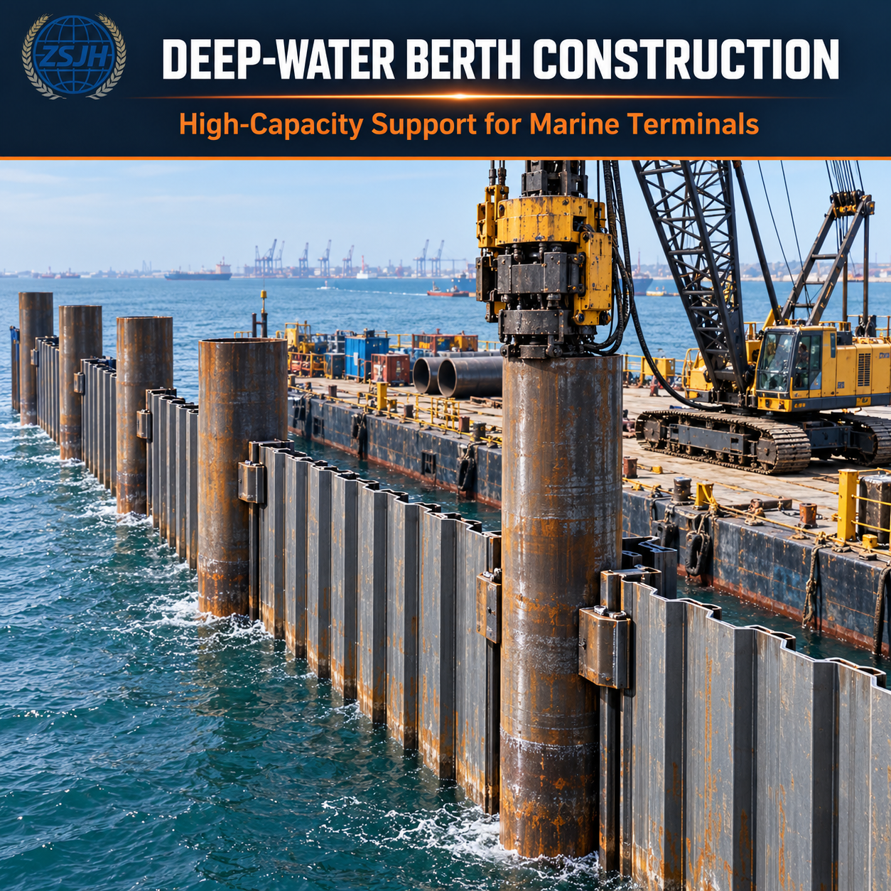
Construction in deep water
Strict deformation control
System selection should consider:
Soil stratification
Groundwater and water depth
Dredge level
Scour depth
Retained height
Berth surcharge
Seismic actions
Wave and current effects
Berthing and mooring loads
Anchor arrangement
Design life
Corrosion exposure
Installation equipment
Adjacent infrastructure
| Parameter | Available Specification |
|---|---|
| Product Name | Combined Steel Sheet Pile Wall System |
| System Type | H-section king-pile wall, tubular king-pile wall or project-specific combi-wall |
| Primary Element | Hot-rolled, tubular or fabricated structural steel king pile |
| Infill Element | Compatible U-type or Z-type interlocking sheet pile |
| Connector | Welded or project-specified interlock connector |
| King-Pile Steel Grade | According to the applicable structural-steel standard |
| Infill-Pile Steel Grade | According to the specified sheet-piling standard |
| Connector Material | Compatible structural steel according to the approved design |
| King-Pile Size | According to structural and geotechnical design |
| King-Pile Spacing | Project-specific |
| Infill-Pile Profile | Selected according to span, pressure and installation requirements |
| Section Properties | According to the confirmed system configuration |
| Component Length | Project-specific and subject to manufacturing and transportation limits |
| Surface Condition | As rolled, blasted, coated or otherwise protected by agreement |
| Welding | According to approved drawings, welding procedures and inspection requirements |
| Splicing | Workshop or site splicing according to approved engineering details |
| Corrosion Protection | Coating, corrosion allowance, cathodic protection or combined strategy |
| Dimensional Tolerances | According to applicable standards and project specifications |
| Inspection Documents | According to the purchase order |
| Identification | Component and installation-sequence marking by agreement |
| Packaging | Suitable supports, separators and securing for transport |
The table describes available supply categories. It does not represent one universal combi-wall size.
King-pile spacing, infill-pile span, wall capacity, section modulus, embedment and anchor forces must be calculated for the specific project.
Depending on the system configuration, the order may reference different standards for individual components, including:
EN 10248 for hot-rolled steel sheet piles
EN 10249 for cold-formed steel sheet piles
EN 10025 for certain structural-steel products
EN 10210 or EN 10219 for specified hollow sections
ASTM sheet-piling and structural-steel specifications
JIS, GB or other agreed national standards
Project-specific welding and fabrication requirements
Standards from different systems must not be treated as automatically equivalent. Each component’s grade, dimensions, tolerances, testing and documentation must be confirmed separately.
King piles should be checked for:
Bending
Shear
Axial force where applicable
Combined loading
Buckling
Lateral-torsional stability where relevant
Driving stresses
Local connector forces
Splice capacity
Corrosion-related section loss
Infill sheet piles should be verified for:
Bending between king piles
Interlock compatibility
Installation stresses
Soil and water pressure
Required penetration
Seepage-control requirements
Corrosion allowance
Connector engagement
Anchored combined walls require coordinated design of:
Tie rods or ground anchors
Waling beams
Connection plates
Anchor walls or deadmen
Prestressing requirements
Construction-stage loading
Corrosion protection
Inspection access
Wall deflection and settlement can be as important as ultimate structural capacity. Design should consider the effect of movement on:
Crane rails
Pavements
Utilities
Buildings
Capping beams
Fender systems
Adjacent marine structures
The approved system layout, king-pile sections, connector orientation, component lengths, welding details and identification requirements are reviewed before fabrication.
H-sections, steel pipes, plates, connectors and sheet piles are selected according to the specified grades and standards.
Raw materials may be checked for:
Material certificates
Steel grade
Dimensions
Wall or flange thickness
Straightness
Surface condition
Product identification
Components are cut to the ordered length. Beveling, end squaring or splice preparation is completed where required.
Interlock connectors are positioned along the king pile using fixtures or controlled measurement. Correct alignment is important for installing the infill piles.
Connectors are welded according to approved welding procedures. Welding sequence and heat input should be controlled to reduce distortion.
Where full-length elements require splicing, the splice is prepared according to approved structural drawings and welding requirements.
Finished components are checked for:
Overall length
Connector position
Connector orientation
Straightness
Sweep and camber
Splice geometry
End condition
Inspection may include visual examination and specified nondestructive testing according to the applicable inspection plan.
Where required, components are blast cleaned and coated according to the confirmed surface-preparation and coating specification.
Each component may be marked according to wall position or driving sequence. Suitable supports and separators are used to protect connectors during transport.
A typical installation sequence may include:
Surveying and setting out the wall alignment.
Installing a guide frame or piling template.
Pitching and driving the first king pile.
Installing subsequent king piles at controlled spacing.
Checking pile alignment and connector orientation.
Threading the intermediate sheet piles into the connectors.
Driving the infill piles to the required level.
Installing walers, tie rods, anchors or internal bracing.
Completing backfilling, dredging or excavation in the approved sequence.
Constructing the capping beam and associated marine components.
Monitoring wall movement and anchor forces where required.
The exact sequence depends on soil conditions, water depth, equipment and structural design.
The installation method should address:
King-pile lifting and pitching
Pile-driver capacity
Vibratory or impact driving
Guide-frame stiffness
King-pile spacing
Connector protection
Infill-pile threading
Pile verticality
Driving refusal criteria
Hard layers and obstructions
Marine currents and tides
Splicing procedures
Noise and vibration restrictions
Installation tolerances
Construction-stage stability
Primary pile deviation can make it difficult to install the infill elements. Surveying, templates and driving control are therefore essential.
A combined wall may pass through atmospheric, splash, tidal, immersed and buried exposure zones. Each zone can have a different corrosion rate.
Durability measures may include:
Design corrosion allowance
Protective coating
Higher-performance coating in splash and tidal zones
Cathodic protection
Concrete encasement or capping
Replaceable protective plates
Inspection and maintenance planning
Selection of an appropriate steel grade
Service life should be assessed using the actual exposure environment and maintenance strategy. It should not be claimed solely from the original steel thickness.
The interlocked infill system can reduce the movement of retained material and restrict water passage. It should not automatically be described as completely watertight.
Possible seepage-control measures include:
Interlock sealants
Selected joint welding
Grouting
Drainage layers
Filter materials
Relief systems
Pumping
Water-level monitoring
The required system depends on soil permeability, hydraulic head and allowable leakage.
Large primary piles can provide substantial stiffness for demanding wall geometries and load conditions.
Different structural functions are assigned to the king piles and infill piles, allowing engineers to optimize the complete wall.
The system can be configured with different king-pile types, infill sections, connectors and anchor arrangements.
Combined walls can be considered for deep-water and deep-excavation applications when supported by appropriate design and installation equipment.
Connectors, splices, lifting details, surface preparation and component marking can be coordinated before delivery.
Position-based marking can help site teams organize the driving sequence and distinguish different component lengths or connector arrangements.
Steel components can enter established recycling channels at the end of their useful life, subject to local recovery practices.
ZSJH can coordinate:
H-section or tubular king piles
Project-specific fabricated sections
U-type or Z-type infill piles
Connector selection and orientation
Customized component lengths
Workshop splicing
Lifting-hole or lifting-lug preparation
Surface preparation
Marine coating systems
Component numbering
Welding inspection
Nondestructive testing
Export packing and transport supports
All customized work must be based on approved drawings and purchase specifications.
It is a wall formed from regularly spaced high-capacity king piles connected by intermediate sheet piles. The king piles provide the main structural stiffness, while the infill piles retain soil and complete the wall.
An H-pile system uses heavy H-sections as the primary elements. A tubular system uses large steel pipes fitted with interlock connectors. Selection depends on structural demand, axial loading, stiffness, availability and installation conditions.
No. H-section and Z-infill systems are one category of combined wall. Tubular king-pile systems and other fabricated configurations are also available.
Spacing depends on king-pile capacity, infill-pile span, earth and water pressure, wall height, anchor configuration, deformation limits and installation tolerances.
They may contribute to vertical load resistance when specifically designed and verified for axial loading, soil resistance and combined actions. This must not be assumed for every system.
Yes. They transfer forces and provide engagement between the king piles and infill piles. Connector material, weld design, alignment and inspection must follow the approved specification.
Yes, provided corrosion allowance, coatings, cathodic protection and maintenance requirements are designed for the actual marine environment.
Standard interlocks are not inherently completely watertight. Sealing, welding or another engineered seepage-control method may be needed.
Long components may be supplied subject to production, lifting and transportation capabilities. Workshop or approved site splices may be required.
Please provide:
Wall layout and piling schedule
King-pile type and section
Infill-pile profile
Connector type and orientation
Steel grades and standards
Individual component lengths
Quantities
Splice requirements
Welding and inspection requirements
Corrosion-protection specification
Component marking requirements
Destination port
Delivery schedule
ZSJH can coordinate king piles, infill sheet piles, connectors, fabrication and related steel components according to confirmed project requirements.
Connector positions, orientations, component lengths and splice details are prepared according to approved drawings.
Material verification, dimensional inspection, connector alignment, welding control, surface inspection and marking checks are incorporated into production.
Cutting, connector welding, splicing, surface preparation, coating and component identification can be coordinated within the agreed scope.
Long and heavy components are prepared with suitable supports, separators, markings and shipping arrangements.
ZSJH supports technical clarification, drawing review, quotation preparation, production coordination, inspection documentation and international delivery.
Send ZSJH your approved wall layout, piling schedule, king-pile section, infill-pile profile, connector details, steel grades, component lengths, quantities, welding requirements, corrosion-protection specification and destination port.
If the system has not yet been finalized, please provide the intended application, water depth, dredge level, retained height, soil report, design loads, anchor arrangement, required service life and installation limitations.
ZSJH can assist with available supply and fabrication options. Final structural capacity, pile spacing, embedment, anchor system and construction method must be approved by the project’s qualified structural, geotechnical and marine engineers.


