:sales@zsjhsteelgroup.com WhatsApp:+86-15122582058








| Quantity: | |
|---|---|


ZSJH
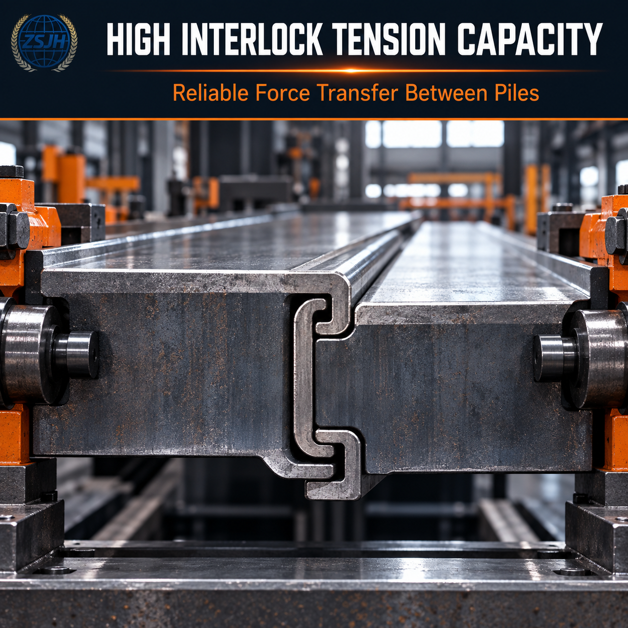
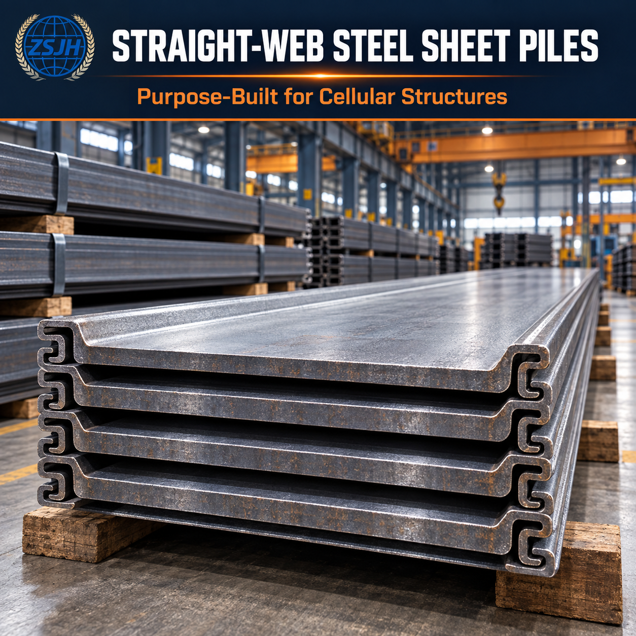
The pile consists of a broad, substantially flat steel web with hot-rolled interlocks formed along both longitudinal edges. The profile is intended to accommodate the curved geometry of cellular structures through controlled rotation within the interlocks.
When a closed cell is filled, the fill produces outward pressure against the steel perimeter. This pressure creates circumferential tension within the cell wall.
Straight-web piles transfer this force primarily through their webs and interlocks. For this reason, interlock tensile capacity is a critical design and product-selection parameter.
A cellular structure does not behave in the same way as a conventional cantilever sheet-pile wall. Its stability depends on the complete system, including:
Cell geometry
Pile embedment
Internal fill weight
Fill shear resistance
Foundation-soil properties
Sliding and overturning resistance
Interlock tensile capacity
Water-pressure conditions
Scour protection
Construction sequence
The allowable rotation or swing at the interlocks enables the piles to form curved walls. The required curvature must remain within the limits of the selected pile section and interlock system.
The straight-web profile is specifically suited to closed circular cells and diaphragm-type cellular systems.
Integral hot-rolled interlocks transfer tensile forces between adjacent piles when the cellular structure is subjected to internal fill pressure.
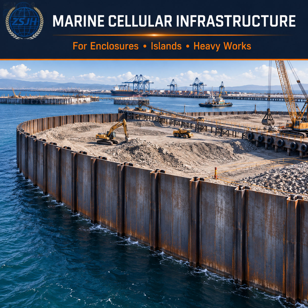
The system can be used for extensive waterfront enclosures, artificial islands, cofferdams and other projects requiring substantial plan dimensions.
Once properly installed and filled, cellular structures can provide stability through their geometry, fill mass and foundation interaction without relying solely on conventional external anchors.
Circular cells, connecting arcs and diaphragm cells can be configured to suit different site boundaries and project functions.
Pile length can be selected according to the required wall height, embedment, foundation conditions, handling limits and transportation arrangements.
Straight-web piling may be used in permanent marine structures or temporary cellular cofferdams, depending on project design.
Hot-rolled straight-web steel sheet piles are commonly considered for:
Circular cellular cofferdams
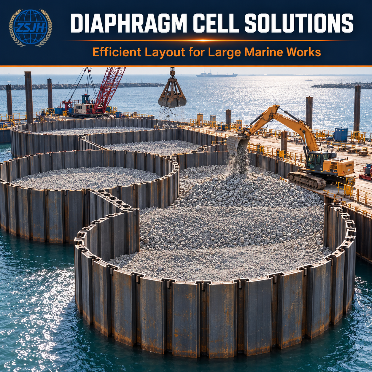
Diaphragm-type cellular structures
Marine construction enclosures
Artificial-island perimeters
Bridge-pier and bridge-foundation works
Navigation-lock construction
Dam and hydropower construction works
Breakwater and harbor structures
Large quay and terminal developments
Offshore and nearshore working platforms
Earth-filled marine retaining cells
Closure cells and connecting arcs
Temporary dewatering enclosures
River-diversion structures
Heavy industrial waterfront projects
Straight-web sheet piling is generally selected for large civil and marine works requiring a closed or connected cellular system.
The product may be suitable where the project requires:
Large unsupported marine enclosures
High interlock tensile resistance
Circular or curved steel cell walls
Earth- or granular-filled gravity structures
Construction in water or difficult access areas
Temporary dry working areas
Permanent waterfront reclamation
Heavy construction platforms
Connection between multiple primary cells
The suitability of the system must be verified against the site-specific soil, hydraulic, structural and construction conditions.
| Parameter | Available Specification |
|---|---|
| Product Name | Hot-Rolled Straight-Web Steel Sheet Pile |
| Alternative Description | Flat-web or straight-web sheet pile |
| Product Form | Broad flat web with integral interlocks on both edges |
| Primary Function | Tensile force transfer in cellular structures |
| Manufacturing Method | Hot rolled |
| Steel Type | Structural carbon steel or project-specified structural steel |
| Steel Grade | Selected according to the specified standard and design requirements |
| Common EN Grade Options | S240GP, S270GP, S320GP, S355GP, S390GP or S430GP, subject to product availability |
| Other Grade Systems | ASTM, JIS, GB or project-specified grades by agreement |
| Reference Standard | EN 10248 or another agreed product standard |
| Nominal Pile Width | According to the selected straight-web profile |
| Web Thickness | According to the selected straight-web profile |
| Interlock Geometry | According to the selected pile system |
| Interlock Tensile Capacity | According to the confirmed manufacturer’s technical data and test requirements |
| Allowable Interlock Rotation | According to the selected profile and system data |
| Cross-Sectional Area | According to the selected profile |
| Unit Mass | According to the selected profile |
| Length | Project-specific, subject to manufacturing and transportation capabilities |
| Surface Condition | As rolled; optional preparation or protective treatment by agreement |
| End Condition | Mill cut, saw cut or project-specified preparation |
| Fabrication Options | Lifting holes, approved cutting, welding or connection preparation |
| Dimensional Tolerances | According to the applicable product standard |
| Inspection Documents | According to the purchase specification |
| Marking | According to the order and traceability requirements |
| Packaging | Secured bundles for lifting and export transportation |
The specifications above describe available supply categories rather than fixed values. Width, thickness, unit mass, interlock strength, rotation capacity and other section data must be taken from the confirmed technical datasheet for the selected pile model.
Steel grades specified under different standards are not automatically equivalent. The applicable standard, steel grade, mechanical properties and inspection requirements must be stated in the purchase order.
Circular cells are formed by connecting straight-web piles into a closed ring. The cells are installed and subsequently filled with suitable granular material.
Depending on the project layout, adjacent primary cells may be connected with curved arc sections. Circular cellular structures are commonly used for cofferdams, marine enclosures and large waterfront works.
Diaphragm-type structures typically consist of curved outer walls connected by straight diaphragm walls. This arrangement creates a sequence of connected cells and can suit long marine structures or specific site geometries.
Connecting arcs may be installed between primary cells to create a continuous enclosure. Special junction piles or fabricated connection elements may be required where wall directions change or different cell components intersect.
Connection geometry must be coordinated with the selected sheet-pile system and engineering design.
Interlock tensile capacity is one of the principal parameters for straight-web sheet piles. The required capacity depends on cell diameter, internal fill pressure, external water or soil pressure and the overall structural model.
Values must be confirmed from the selected pile manufacturer’s technical documentation. They should not be assumed from steel yield strength alone.
The ability of adjacent piles to rotate within their interlocks allows the wall to follow a curved plan. Excessive rotation can reduce engagement reliability or exceed the product’s permissible geometry.
The allowable rotation for the selected section must be checked before finalizing the cell diameter and layout.
Pile length is determined by:
Required cell height
Water depth
Foundation level
Required toe embedment
Scour depth
Seepage-control requirements
Construction tolerance
Handling and driving requirements
The completed cell should be checked for:
Sliding
Overturning
Bearing resistance
Foundation failure
Internal fill shear failure
Interlock rupture
Excessive deformation
Pile-toe displacement
Scour and erosion
Seepage and piping
Construction-stage instability
Steel chemistry is controlled according to the required grade. The molten steel is cast into suitable semi-finished products for rolling.
The semi-finished steel is reheated under controlled conditions to achieve the temperature required for hot forming.
Oxide scale is removed using suitable high-pressure descaling equipment before and during profile formation.
The heated material passes through a sequence of specially shaped rolling stands. The central web and integral edge interlocks are progressively formed into the specified straight-web profile.
The finished profile is cooled under controlled production conditions to support the required dimensional and material characteristics.
Mechanical straightening equipment controls pile alignment, sweep and camber according to the applicable tolerances.
The piles are cut to the ordered project length. Additional end preparation may be completed when included in the approved purchase specification.
Inspection may include:
Chemical-composition verification
Mechanical-property testing
Web-width and thickness inspection
Length and straightness checks
Unit-mass verification
Surface-condition inspection
Interlock-dimension inspection
Interlock-engagement testing
Product marking and document review
Specified interlock tensile testing when required by the order
Finished piles are aligned, securely bundled and marked to support identification, lifting, storage and international transportation.
The center, diameter, connecting arcs and diaphragm lines are established according to the approved construction drawings.
A sufficiently rigid guide frame or template is installed to maintain the required cell geometry, pile alignment and verticality.
The first piles are carefully positioned. Their alignment is critical because initial errors can accumulate around the cell perimeter.
Each pile is threaded into the preceding interlock and positioned according to the planned cell curvature.
Piles may be installed using vibratory, impact or press-in equipment, subject to soil conditions, equipment capacity and environmental restrictions.
The final closure requires accurate control of pile spacing, accumulated interlock rotation and wall alignment. A planned closure sequence or special closure pile may be required.
Approved granular fill is placed according to the engineered sequence. Fill placement should be controlled to avoid excessive imbalance and unintended deformation of the perimeter wall.
Compaction requirements depend on the fill material and structural design. Placement and compaction should follow the approved method statement.
Cell geometry, interlock condition, pile movement, fill elevation and surrounding water or soil behavior should be monitored during construction.
A project-specific installation method should address:
Pile-driving equipment
Crane and lifting capacity
Guide-template stiffness
Pile verticality
Interlock orientation
Accumulated cell circumference
Closure tolerances
Soil obstructions
Driving resistance
Interlock damage
Fill-placement sequence
Differential fill levels
Tidal and current conditions
Temporary construction stability
Worker and marine-operation safety
The installation sequence is an engineering component of the cellular system and should not be changed without technical review.
Straight-web sheet piles used in marine structures may be exposed to atmospheric, splash, tidal, immersed and buried corrosion zones. These zones can experience different corrosion conditions.
Possible durability measures include:
Design corrosion allowance
Protective coating systems
Abrasive blasting and specified surface preparation
Cathodic protection
Concrete capping or facing in selected zones
Selection of a suitable steel grade
Inspection and maintenance planning
Coating type, preparation grade, dry-film thickness and application zones must be defined by the project specification. No universal service-life claim should be made without considering the actual exposure environment and maintenance plan.
Interlocked steel sheet piles can reduce soil movement and water passage, but standard interlocks are not inherently completely watertight.
Depending on project requirements, seepage management may include:
Compatible interlock sealants
Specified welding of selected joints
Internal drainage
Pumping systems
Filter layers
Grouting
Seepage monitoring
The correct method depends on water pressure, soil permeability, temporary or permanent use and the allowable leakage rate.
The straight-web profile is designed for the tensile load path associated with filled cellular structures.
Multiple cells and connecting arcs can create extensive marine platforms, cofferdams or reclamation boundaries.
Pile interlock rotation permits circular and curved arrangements within the limitations of the selected profile.
Properly designed cellular structures obtain stability from cell geometry, internal fill and foundation interaction. External anchoring requirements depend on the specific design.
The system combines structural steel, integral interlocks and project-specific corrosion protection for demanding infrastructure environments.
Pile grade, profile, length, surface treatment and inspection requirements can be coordinated according to the confirmed technical specification.
Steel piles can enter established recycling channels after their usable service life, subject to local recovery practices.
ZSJH can coordinate the following options according to the approved order:
Straight-web profile selection
Steel grade
Applicable manufacturing standard
Project-specific pile length
Surface preparation
Protective coating
Lifting-hole preparation
Pile-end cutting
Special marking and traceability
Inspection-document requirements
Testing requirements
Export bundling and shipping arrangements
Special junction, closure or connection elements must be manufactured according to approved drawings and welding requirements.
Straight-web piles are primarily designed to transfer tensile forces through their interlocks in cellular structures. U-type and Z-type piles are more commonly used as bending members in conventional retaining walls. They should not be treated as interchangeable without engineering verification.
Stability is provided by the combined behavior of the steel perimeter, internal fill, cell geometry, pile embedment and foundation soils. The structure must be checked for sliding, overturning, bearing, internal shear and other applicable failure modes.
Internal fill pressure creates circumferential tension in the cell wall. This force passes between adjacent piles through their interlocks, making interlock tensile capacity a critical design parameter.
No. The possible diameter is influenced by pile width, number of piles and permissible interlock rotation. The geometry must be checked against the selected pile system.
Standard interlocks are not inherently completely watertight. Sealants, welding, pumping, drainage or other seepage-control measures may be required.
Fill type, grading, density, drainage properties and placement method must be determined by the geotechnical and structural design. Suitable granular materials are commonly used, but the final specification is project-specific.
Yes, provided the steel section, corrosion allowance, surface protection and maintenance strategy are designed for the actual marine environment and required service life.
Yes. Lengths can be coordinated according to the approved piling schedule, subject to manufacturing, handling and transportation limitations.
Maintaining the correct cell geometry and completing the final closure are often critical. Accurate surveying, rigid templates and controlled interlock rotation are essential.
Please provide:
Straight-web pile profile or required properties
Applicable product standard
Steel grade
Individual pile length
Number of piles or total quantity
Cell layout or piling schedule
Interlock tensile requirements
Surface-treatment requirements
Testing and inspection requirements
Special junction details
Destination port
Delivery schedule
ZSJH supplies steel products for marine, foundation, retaining and cellular construction projects.
Our team can assist in reviewing the requested pile profile, steel grade, length, interlock requirements, surface condition and inspection documentation.
Chemical composition, mechanical properties, product dimensions, length, surface condition, interlocks, marking and documentation can be checked according to the confirmed order.
Project-specific cutting, lifting holes, surface treatment, marking and approved connection preparation can be coordinated when required.
The piles are bundled and identified according to their length, handling requirements and international transportation route.
ZSJH supports technical clarification, quotation preparation, order confirmation, production coordination, documentation and shipping communication.
Send ZSJH your approved cell layout, piling schedule, required straight-web profile, steel grade, standard, pile length, quantity, interlock tensile requirement, surface treatment, inspection requirements and destination port.
If the pile profile has not yet been selected, please provide the proposed cell type, diameter, wall height, water depth, soil report, internal fill properties, design loads, required service life and construction conditions.
ZSJH can assist with available supply options and product-document coordination. Final cell geometry, structural capacity, foundation stability and construction method must be approved by the project’s qualified structural, geotechnical and marine engineers.


