:sales@zsjhsteelgroup.com WhatsApp:+86-15122582058





| Quantity: | |
|---|---|


ZSJH
Custom steel frameworks for multi-tier cable tray and cable ladder installations.
ZSJH STEEL supplies Industrial Steel Cable Rack Structures for factories, processing facilities, industrial parks, and utility areas. Our structural steel package includes support columns, multi-level crossbeams, cantilever arms, bracing, connection plates, and column base plates.
Each structure is fabricated to approved project drawings, with its layout coordinated around cable tray routes, specified support loads, mounting elevations, and installation clearances.
| Component | Function and Supply Details |
|---|---|
| Multi-Tier Support Frames | Repeated steel frames providing designated support levels for parallel cable tray or cable ladder routes. |
| Steel Columns | Upright members supporting crossbeams or cantilever arms, with specified base connections. |
| Horizontal Crossbeams | Transverse members carrying tray support reactions and transferring loads to the columns. |
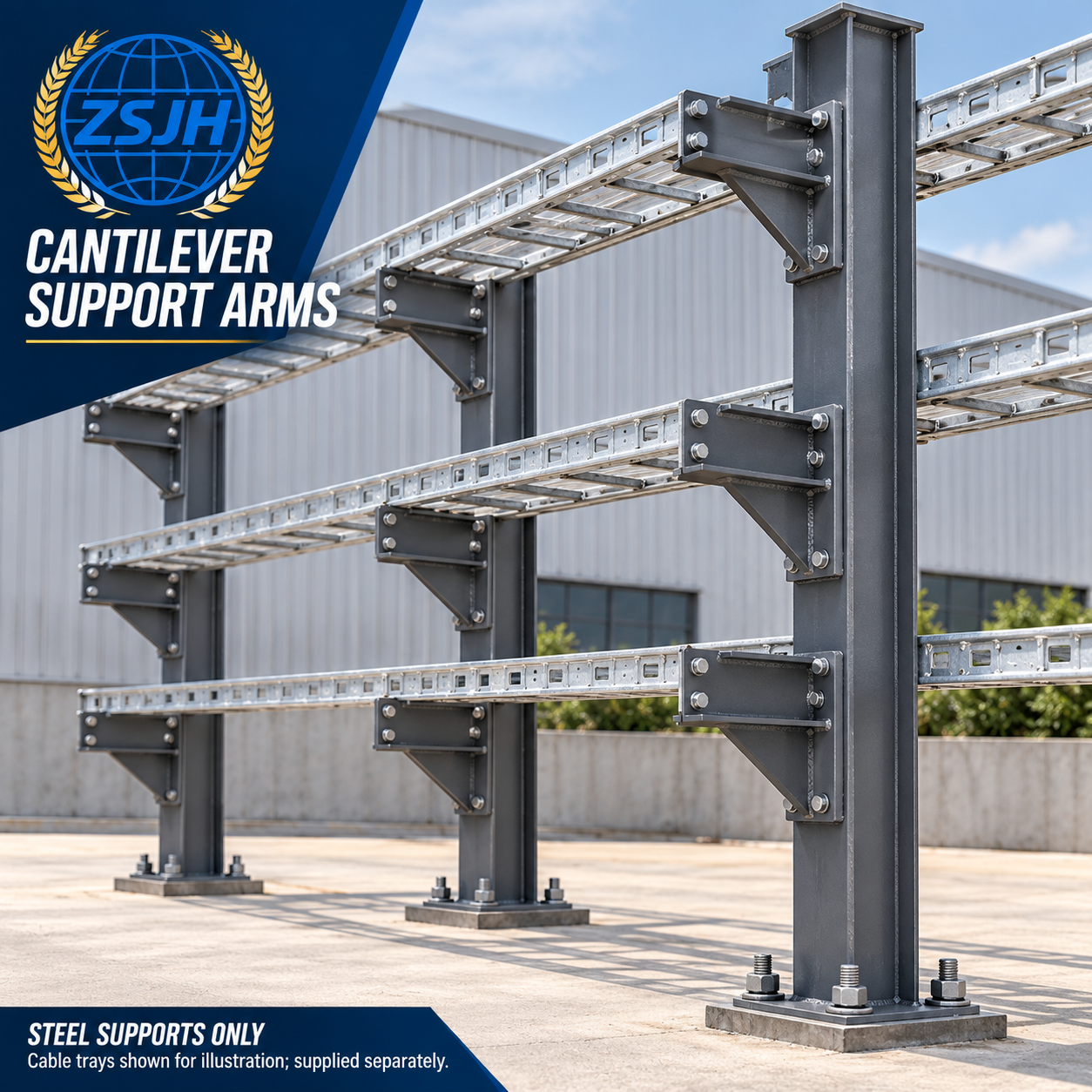
| Cantilever Support Arms | Project-specific brackets extending from columns or approved supporting structures. |
| Bracing Members | Diagonal braces and longitudinal ties forming the specified stability system. |
| Connection Assemblies | End plates, cleats, gusset plates, stiffeners, and bolted or welded joints according to approved details. |
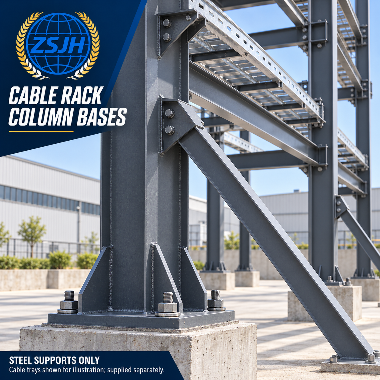
| Column Base Plates | Fabricated base plates and stiffeners coordinated with the foundation anchorage arrangement. |
Support frames can accommodate several cable tray levels within a defined structural envelope. Tier elevations, frame spacing, and crossbeam lengths are configured to suit the approved electrical layout.
Coordination considers:
Tray widths, quantities, and routing.
Specified tray and cable loads.
Allowances for future installation where required.
Clearance for cable installation and tray maintenance.
Changes in direction, elevation, and support conditions.
Interfaces with adjacent buildings and equipment.
Electrical separation distances, cable bending requirements, and routing criteria are established by the project’s electrical designer and incorporated into the structural arrangement.
Crossbeams provide support across a frame, while cantilever arms can carry trays along one or both sides of a column where specified.
Member sizes and support spacing follow the approved loading and structural design. The steel frame layout must also remain compatible with the selected tray system’s permitted spans and mounting requirements.
Tray attachment provisions can include mounting holes, cleats, or brackets. Slots and adjustment details are provided only where shown on approved drawings.
Connections are detailed to transfer the specified forces between columns, beams, support arms, and braces. Depending on the project, the package can incorporate:
Bolted beam-to-column end plates or cleats.
Reinforced cantilever arm connections.
Bracing gusset plates.
Column and beam splices.
Base plates with specified anchor-hole patterns.
Components can be marked for site identification, with transportable assemblies arranged around shipment and erection requirements. Site alterations require review before implementation.
The supporting steelwork and cable tray system are coordinated as separate supply elements.
Before fabrication, the selected tray supplier’s support locations, attachment details, movement provisions, and loading information should be confirmed. Earthing and bonding provisions are included in the steelwork only where specifically detailed; electrical continuity must not be assumed from structural connections alone.
| Item | Project Options |
|---|---|
| Frame Configuration | Portal-type frames, cantilever arrangements, or combined systems |
| Number of Tiers | According to the approved cable routing layout |
| Structural Members | Rolled sections, welded sections, hollow sections, and fabricated plate assemblies |
| Steel Grade | Q235B, Q355B, or other specified grades, subject to approval and availability |
| Connections | Shop-welded assemblies and site-bolted connections as detailed |
| Surface Protection | Project-specified paint systems or hot-dip galvanizing where suitable |
| Access Components | Inspection platforms, stairs, and guardrails where separately specified |
| Delivery Form | Marked components or transportable assemblies |
Final member dimensions, material standards, fabrication tolerances, and protective treatments follow the agreed project specifications.
The standard scope covers the load-bearing steel support structure only.
Cable trays and cable ladders shown in product images illustrate the intended installation. Unless expressly listed in the quotation, the following are excluded:
Cable tray and cable ladder bodies.
Tray covers, bends, tees, reducers, and tray splice accessories.
Cables, cable cleats, and electrical fittings.
Earthing conductors and bonding accessories.
Electrical installation, testing, and commissioning.
Concrete foundations and civil works.
Structural bolts, anchor bolts, tray attachment brackets, and access components are included only as identified in the agreed bill of materials. Cable trays or ladders can be quoted as a separate scope when requested.
Factory power and control cable routes.
Processing plant electrical distribution areas.
Industrial park utility corridors.
Equipment service areas.
Elevated cable routes between industrial buildings.
Agreed inspection activities can include material document review, dimensional checks, weld inspection, bolt-hole verification, and coating inspection.
Particular attention is given to tier elevations, crossbeam positions, bracket alignment, and mounting interfaces. Components are identified and packaged according to the agreed delivery and site assembly plan.
Is this a cable tray product?
This product is the structural steel framework supporting cable trays or cable ladders. The tray system itself is a separate supply item unless agreed otherwise.
Can you fabricate to our electrical routing drawings?
Routing drawings can be used for coordination. Fabrication requires approved structural details, loads, and tray mounting information.
Can the structure allow for future cable expansion?
Yes, where the additional loads, tray positions, and space allowances are defined and included in the approved design.
Can the supports attach to an existing building?
Yes, subject to verification of the existing structure and approval of the proposed loads and connections.
ZSJH STEEL coordinates structural detailing, fabrication, inspection, surface treatment, and export preparation within a clearly defined supply scope. Our focus is on accurate support elevations, coordinated tray interfaces, and clearly identified steel components for site assembly.
Please provide the cable routing layout, tray dimensions, tier elevations, support loads, required frame spacing, mounting details, site design criteria, coating requirements, and delivery destination.
Contact ZSJH STEEL for a project-specific Industrial Steel Cable Rack Structure quotation.


