:sales@zsjhsteelgroup.com WhatsApp:+86-15122582058


Views: 0 Author: Site Editor Publish Time: 2026-08-31 Origin: Site


Structural load transfer goes far beyond abstract physics. It serves as the definitive metric for building safety, operational lifespan, and overall commercial viability. Understanding these load paths remains absolutely critical. You need this deep knowledge to evaluate complex architectural designs confidently. It also proves essential when comparing different fabrication vendors. Furthermore, mapping these physical forces helps you proactively manage severe project risks. We will step away from purely theoretical engineering concepts today. Instead, we provide a robust, decision-stage evaluation framework. You will discover exactly how to assess proposed designs. We guide you through verifying if a structural framework can reliably handle your specific operational demands. Your final facility must withstand both daily use and extreme environmental events seamlessly.
A reliable steel structure system relies on a "continuous load path"—channeling weight and environmental stress from the roof seamlessly down to the foundation.
Evaluating a structure requires separate analyses for gravity (vertical) loads and environmental (lateral) forces.
Specifying a prefabricated steel structure shifts load-path risk from unpredictable site conditions to highly controlled factory quality assurance (QA).
High-stress applications demand specialized engineering, making connection design (welds and bolts) the most critical evaluation point for procurement.
Structural engineering aims for one primary outcome. It requires a highly predictable, uninterrupted path for physical weight. Industry professionals call this the continuous load path. Gravity never sleeps. Forces constantly pull materials downward. The building must channel these forces safely into the ground. A successful framework guarantees this downward journey happens without any structural bottlenecks.
This sequential flow follows a strict, unyielding order:
Roof and Floor Decking: These flat surfaces absorb initial impacts. They carry occupant weight and weather accumulation directly.
Joists: Decking transfers its stress into these closely spaced supports.
Beams and Girders: Joists pass their burden down to these primary horizontal members.
Columns: Girders route the accumulated weight securely into vertical supports.
Foundation: Columns deliver all combined building forces deep into the earth.
Buyers must scrutinize digital structural models carefully. You should review Tekla or SAP2000 simulations alongside your engineers. Architectural aesthetics often conflict directly against structural logic. Large open atriums or floating staircases can easily interrupt natural force flow. You must verify these aesthetic features never compromise ultimate safety.
Structural failures rarely happen in the primary members themselves. Raw steel beams inherently possess immense strength. Failures usually occur at connection points. Poor detailing disrupts the continuous path instantly. Missing gusset plates or undersized bolts create catastrophic weak points.
Best Practice: Always demand 3D model clash detection before fabrication begins. This prevents complex architectural elements from obstructing primary load-bearing connections.
We must evaluate structural systems across two distinct force dimensions. Buildings face constant vertical stress daily. They also endure unpredictable horizontal attacks from the environment. Both dimensions require entirely different engineering solutions.
Gravity loads push straight down toward the earth. We divide them into two primary categories. Dead loads represent the permanent weight of the building itself. This includes concrete slabs, heavy steel beams, and thick roofing materials. Live loads represent temporary weights. Occupants, moving inventory, and dynamic equipment fall into this category. You must calculate live loads accurately to prevent long-term floor sagging.
Environmental forces push horizontally against the exterior frame. Wind shear tries to tip the entire building over. Seismic activity shakes the deep foundation violently. Soil pressure pushes laterally against subterranean basement walls. The structure must resist these attacks while maintaining vertical stability.
Scalability completely changes the standard design approach. Consider a multi storey steel frame in an urban environment. It compounds vertical loads significantly at the ground base. The bottom columns must support every single floor above them. Simultaneously, the structure becomes much more vulnerable to lateral sway at the top. Engineers must perfectly balance lower-level compression against upper-level flexibility.
Authoritative standards dictate these specific load assumptions. You must verify full compliance early. Regional mandates like ASCE 7 or Eurocode 3 define minimum safety thresholds. Local seismic codes dictate specific connection flexibility requirements. Do not accept generic load assumptions for your unique project site.
Force Category |
Load Types |
Primary Structural Impact |
Mitigation Strategy |
|---|---|---|---|
Gravity (Vertical) |
Dead Loads, Live Loads, Snow |
Downward compression, floor deflection |
Thicker column profiles, rigid horizontal girders |
Environmental (Lateral) |
Wind Shear, Seismic, Earth Pressure |
Horizontal racking, overturning, structural sway |
Shear walls, cross-bracing, moment connections |
Core components drive the actual mechanics of load transfer. Every individual piece plays a highly specialized role. They work together to maintain the continuous load path.
Beams and Girders: These horizontal members absorb widely distributed weight. They take broad floor loads and channel them into tight, concentrated points. They resist severe bending under heavy stress.
Columns: These act as critical vertical conduits. They must resist severe buckling under immense compressive forces. A failing column often triggers an immediate progressive collapse.
Bracing Systems and Shear Walls: Engineers deploy these specifically for lateral loads. They absorb horizontal wind and seismic energy effectively. They prevent the frame from racking or leaning sideways.
Connections represent the most critical juncture. Bolts, heavy plates, and welds form the actual transfer mechanisms. Massive forces must cross these tiny bridges between large structural members. This creates the highest-risk area in any steel structure system. Connections demand rigorous inspection protocols. A slightly under-torqued bolt can completely derail the engineered load path.
High-stress environments require entirely different engineering rules. Standard commercial frames will fail rapidly under intense industrial demands.
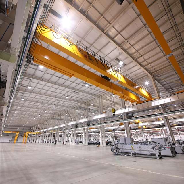
Identify your specific use case early in the planning phase. You might require a specialized heavy load steel structure. Manufacturing plants house massive stamping presses. Warehouses utilize heavy overhead bridge cranes constantly. Industrial platforms support vibrating mining equipment. These applications introduce severe, unrelenting operational stress.
Dynamic load management becomes critical here. Moving machinery creates constant structural vibration. It introduces severe fatigue stress into the main joints. You cannot rely on standard I-beams for these intense applications. Engineers must modify cross-sectional profiles significantly. They frequently specify complex built-up sections. They deploy heavy H-columns to resist constant shaking.
Connect these specialized features directly to operational outcomes. Higher material yield strengths prevent microscopic tearing over time. Specialized eccentric bracing absorbs machinery vibrations safely. These structural upgrades ensure continuous, safe industrial operations. They actively prevent sudden fatigue failures after years of heavy commercial use.
Common Mistake: Never underestimate the impact of crane runway loads. Bridge cranes exert massive braking forces horizontally along the high tracks. Your structural frame must absorb these sudden stops without dangerous swaying.
Site conditions often introduce severe risks to structural integrity. Unpredictable weather ruins field weld quality. Rushed crews occasionally miss critical bolt tensioning steps. We mitigate these variables through advanced off-site manufacturing methods.
A prefabricated steel structure offers massive safety advantages. Manufacturing takes place in highly controlled indoor environments. Robotic lasers ensure incredibly precise cutting tolerances. Certified welders operate under ideal lighting and temperature conditions. This significantly improves the reliability of all crucial load-transfer connections. Factory quality assurance removes chaotic construction site variables.
However, rollout and erection still carry distinct risks. Field assembly remains a challenging process. Erection tolerances can drift slightly during high winds. Minor baseplate misalignments disrupt the engineered vertical path. Bolt-torquing errors weaken crucial moment connections instantly. Your team must monitor the final assembly obsessively.
Demand strict quality control protocols from your vendors. Trust requires absolute technical verification. Mandate Non-Destructive Testing (NDT) on all critical factory welds. Use ultrasonic testing to find hidden internal metal flaws. Require strict anchor bolt surveying before the first column arrives on site. The concrete foundation must align perfectly accurately.
Procurement dictates ultimate structural safety. Choosing the right partner matters much more than selecting cheap materials.
Evaluate vendors based on strict technical criteria. Assess their specific track record in managing complex load transfers. Do they usually build simple retail shells? If so, they might struggle greatly managing a vibrating industrial facility. Ask for detailed case studies involving heavy dynamic loads.
Maintain completely transparent design assumptions. Clearly define all operational live loads during the initial schematic phase. Specify the exact weights of your specialized machinery. Detail the travel paths of heavy forklifts. This transparency prevents costly retrofits during late-stage construction.
Take decisive next-step actions now. Request preliminary structural calculations before signing final contracts. Review their proposed connection details thoroughly. Audit the fabricator's internal quality management system personally. Ensure they carry recognized credentials like AISC certification. Do not leave foundational safety to chance.
A sound load transfer framework remains absolutely non-negotiable. It guarantees life safety, regulatory compliance, and maximum asset longevity. Every component must guide operational weight seamlessly into the foundation.
Architectural aesthetics must always yield to uncompromising physics. A beautiful open atrium means nothing if it interrupts primary vertical supports. You must prioritize the continuous path above all visual design preferences.
Initiate a rigorous technical consultation today. Engage certified structural engineers and experienced fabricators early. Validate your specific project requirements against established physical realities. Secure your overall investment by securing the load path first.
A: An interrupted path causes immediate load redistribution. The structural weight aggressively seeks alternative routes to the foundation. This severely overloads secondary members not designed for such stress. It often results in localized structural failure. In severe cases, it triggers a catastrophic progressive collapse.
A: Tall buildings rely on specialized lateral force-resisting systems. Engineers utilize moment-resisting frames to keep beam-to-column joints highly rigid. They also deploy diagonal braced frames to absorb horizontal energy. Many structures incorporate stiff concrete core walls. These elements work together to minimize sway and prevent overturning.
A: Yes, they are highly safe and often preferred. Prefabrication simply represents a controlled manufacturing method, not a capacity limitation. Custom pre-engineered buildings utilize high-strength built-up sections. Factory environments ensure superior weld penetration and strict quality control, making them highly effective for demanding industrial environments.
A: Engineers utilize advanced structural analysis software, such as Tekla or SAP2000. They simulate various gravity and environmental force combinations. The software identifies high-stress zones and potential connection vulnerabilities. Final verification requires thorough peer review and official engineering stamps certifying compliance with regional codes.


